Paramhans Industry
September 30, 2026
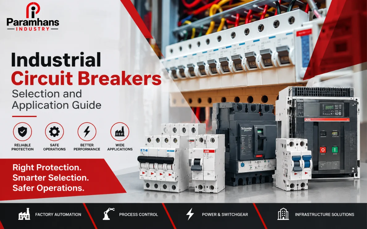
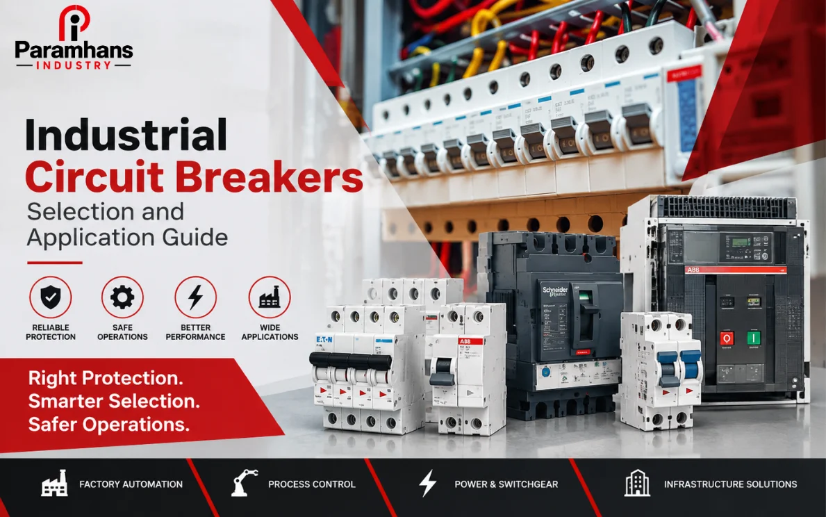
Industrial circuit breakers are switching and protective devices that interrupt current when an electrical circuit experiences an abnormal condition such as overload or short circuit. Depending on the type and application, they may also provide isolation, earth-fault protection, remote operation, status indication and adjustable trip functions. A breaker is not selected by amperes alone: voltage, prospective fault current, conductor capacity, load behaviour, coordination and the installation environment all influence the decision.
Paramhans Industry lists industrial automation and switchgear products, including circuit breakers and related components from multiple brands. Buyers should confirm the exact manufacturer, model, ratings, accessories and current datasheet in the quotation. Similar-looking breakers can differ materially in interrupting capacity, trip curve, poles, approvals, dimensions and permitted accessories.
Main circuit-breaker families used in industry
| Breaker family | Typical role | Selection focus |
|---|---|---|
| MCB | Final circuits and lower-current distribution | Trip curve, breaking capacity, poles and conductor protection |
| MCCB | Feeders, machinery and higher-current distribution | Adjustable protection, fault rating and accessories |
| ACB | Main low-voltage switchboards and high-current incomers | Selectivity, maintainability, draw-out arrangement and control |
| Motor protection breaker | Motor branch protection and manual isolation | Motor range, magnetic threshold and coordination with starter |
| Specialized breaker | Application-specific DC, residual-current or other duty | System voltage, fault behaviour and manufacturer application data |
Miniature circuit breakers
An MCB is compact and commonly used for final distribution circuits. Its rated current and trip characteristic must protect the connected conductor while tolerating expected inrush. The marked breaking capacity must be adequate at the installation point. An MCB is not automatically suitable for an industrial load simply because its current rating matches; load type, ambient temperature, grouping and upstream fault energy may rule it out.
Moulded-case circuit breakers
MCCBs cover a broad range of feeder and equipment duties. Depending on model, their trip unit may offer adjustable long-time, short-time, instantaneous and ground-fault functions. Accessories can include auxiliary contacts, alarm contacts, shunt trip, undervoltage release and motor operators. These capabilities are useful only when they are specified, wired, set and tested as part of the protection scheme.
Air circuit breakers
ACBs are frequently used for main incomers, bus couplers and large outgoing feeders in low-voltage switchboards. Fixed and draw-out arrangements have different space, isolation and maintenance implications. Electronic trip units can support detailed protection and communication, but the project must define power supply, network protocol, event records, settings security and test method. A feature-rich breaker without a coordination plan can still perform poorly.
Nine inputs that determine the correct breaker
1. System voltage, frequency and current type
Confirm nominal and maximum system voltage, AC or DC duty, frequency, earthing arrangement and number of poles that must switch. A breaker rating on an AC system cannot be assumed to apply to DC, because arc interruption and permitted series-pole arrangements differ. For three-phase systems, clarify whether the neutral is switched or protected and how the manufacturer defines the four-pole arrangement.
2. Design current and conductor capacity
Determine the expected continuous load, diversity, future allowance and load profile. The protective setting must coordinate with conductor capacity after correction factors for ambient temperature, grouping and installation method. Oversizing a breaker to avoid nuisance trips can expose the cable to damaging current. Undersizing can interrupt normal operation or prevent the equipment from reaching its intended output.
3. Prospective short-circuit current
Calculate or obtain the fault current available at the breaker location. The breaker must safely interrupt the relevant prospective current at its system voltage. Do not use the transformer rating alone as the final answer; transformer impedance, parallel sources, cable impedance, motors and generators affect the result. If a downstream device relies on an upstream backup relationship, use a tested manufacturer combination rather than an informal assumption.
4. Load starting and inrush behaviour
Motors, transformers, capacitors, welders, power supplies and lighting drivers can draw current above their steady-state value. Compare the time-current characteristic with the starting profile so normal inrush does not cause unwanted operation while genuine faults are cleared promptly. Motor circuits also need overload and phase-loss considerations that may be handled by a coordinated starter, protection relay or motor-protection breaker.
5. Trip unit and adjustment range
A thermal-magnetic unit may suit a straightforward feeder, while an electronic unit can provide finer settings, selectivity and measurement. More adjustment is not automatically better. Settings should come from a protection study and be recorded in an approved schedule. Seal or access-control provisions may be needed so site personnel cannot change a critical protection threshold without authorization.
6. Selectivity and coordination
Selectivity aims to isolate the smallest affected part of the installation. Compare upstream and downstream time-current curves and manufacturer data across overload and short-circuit regions. Total selectivity may not be achievable for every fault level, so the study should state the limit and operating sequence. Coordination also considers contactors, overload relays, fuses, cables and equipment withstand—not only two breakers.
7. Environment and enclosure
Ambient temperature, altitude, dust, humidity, corrosive atmosphere, vibration and enclosure temperature can change permitted ratings or life. A breaker inside a crowded panel may operate warmer than the room. Check manufacturer derating, ventilation, terminal limits and pollution or ingress requirements for the assembled panel. For hazardous areas or special processes, use the project classification and approved equipment strategy.
8. Operating and maintenance needs
Decide whether the breaker must be fixed, plug-in or draw-out; manually or electrically operated; locally reset or remotely controlled. Critical boards may need position indication, interlocking, door operation, test position or communication. Maintenance teams should be able to inspect, test and replace the device safely. The cheapest breaker can create high downtime if spares or trained service are unavailable.
9. Physical and panel compatibility
Verify frame size, terminal orientation, busbar connection, clearances, heat dissipation, handle position, door cut-out and accessory space. Replacement projects require special care: a similar current rating does not make a new breaker mechanically or electrically interchangeable. Update drawings, protection settings, labels and arc-energy information when the design changes.
Breaker selection workflow
| Step | Engineering question | Required evidence |
|---|---|---|
| Define duty | What circuit and operating mode is protected? | Single-line diagram and load data |
| Calculate | What current and fault levels occur? | Load and short-circuit study |
| Coordinate | Which device should trip first? | Curves and manufacturer selectivity tables |
| Specify | Which ratings and accessories are mandatory? | Datasheet and compliance schedule |
| Verify | Does the installed device match the design? | Inspection, settings and test record |
Begin with the approved single-line diagram and circuit duty. Calculate load current, conductor capacity and prospective fault current. Shortlist devices that meet voltage, poles and interruption requirements, then check curves, selectivity, environment and panel fit. Finally, document the exact catalogue number, trip unit, accessories, settings and installation requirements. Procurement substitutions must return to the designer for review.
MCB vs MCCB: the practical decision
MCBs suit many final circuits where compact size, fixed characteristics and standardized modular installation are appropriate. MCCBs serve larger feeders and applications needing higher fault capability, adjustment or accessories. Current rating alone does not define the boundary. A lower-current industrial feeder may still justify an MCCB because selectivity, remote trip or fault duty requires it; a simple final circuit may be adequately protected by an MCB.
Compare the complete duty: rated operational voltage, poles, rated current, breaking performance, trip characteristic, adjustment, accessories, isolation, mounting, standards and life-cycle support. Paramhans also offers a broader power and safety product category, useful when a project needs protection devices and complementary industrial supplies under one procurement scope.
Application examples
Motor feeder
A motor feeder must tolerate starting current and coordinate with the contactor and overload protection while clearing short circuits. Direct-on-line, star-delta and variable-frequency-drive circuits have different current profiles and manufacturer guidance. The breaker should not be chosen as the sole motor-protection element unless the complete device and setting combination provides the required functions.
Transformer feeder
Transformer energization can produce significant inrush, while secondary faults reflect through the turns ratio. The protection study should compare inrush, thermal withstand and fault clearing on both sides. Cable and transformer protection may impose different curve requirements. If the transformer can be energized from more than one source, operating modes must be included.
Capacitor bank and power-electronics load
Capacitors can create energization transients and carry harmonic current, while rectifiers and drives influence waveform and fault behaviour. Use manufacturer recommendations for breaker, contactor and conductor selection. Do not apply a general lighting or motor rule to every electronic load. Confirm whether upstream residual-current or earth-fault devices are compatible with the equipment.
Procurement and installation checklist
- Exact breaker manufacturer, series, frame, catalogue number and current rating are stated.
- System voltage, poles and short-circuit performance match the study.
- Trip-unit type, adjustment ranges and approved settings are documented.
- Auxiliary contacts, releases, motor operator and communication modules are itemized.
- Terminals, lugs, busbar adapters, barriers and interlocks are included where required.
- Panel clearances, ventilation, access and enclosure conditions are verified.
- Factory and site test responsibilities are agreed.
- Drawings, settings, test records and spares are included at handover.
Testing and maintenance
Before energization, verify identity, rating, accessories, wiring, mechanical operation, insulation condition, terminal preparation and torque using approved instructions. Confirm protection settings against the signed schedule and test interlocks, shunt trips, undervoltage releases and status contacts. Primary or secondary injection may be required according to the device and commissioning plan. Record instrument, method, result and acceptance.
Maintenance frequency depends on duty, fault history, environment and manufacturer guidance. Inspect for overheating, contamination, loose connections, mechanical damage and abnormal operation. Exercise and test devices as planned, and investigate every fault trip before reset. Paramhans describes its distributor role and multi-brand support on its About Us page; buyers should define traceability, warranty and service response in the purchase order.
Common selection mistakes
Frequent mistakes include matching only amperes, ignoring the fault level, copying settings from another feeder, using an AC breaker on DC without approval, overlooking inrush, assuming selectivity from brand similarity, omitting accessories and accepting an alternate model without a curve review. Another mistake is specifying maximum breaking capacity but not the application rating and test basis relevant to the system.
Breaker selection and arc-energy risk
Protection clearing time influences incident energy, but a faster setting cannot be applied blindly if it compromises selectivity, motor starting or equipment coordination. An arc-flash assessment may identify maintenance modes, zone-selective interlocking, differential schemes, remote operation or other controls for particular boards. These features require a complete engineering and operating strategy. Labels, personal protective equipment and work procedures should use the approved study and should be updated when the breaker, settings, source or system configuration changes.
Using communication and condition data
Electronic trip units may report current, events, alarms, operating history and breaker condition, depending on the model. Decide which data is useful, how it reaches the control system and who responds. Communication loss must not disable the core protection function. Cybersecurity, time synchronization, access rights and firmware management are part of the deployment. Data can improve maintenance planning, but it does not replace physical inspection, testing or investigation of repeated operations.
Keep an approved setting register linked to the single-line diagram and device asset number. After commissioning or a system change, verify that the physical dial or digital setting still matches the controlled record.
Do not treat a breaker as protection for every electrical hazard. Earthing, bonding, insulation, enclosure, arc-flash risk controls, safe isolation and maintenance practices remain necessary. A qualified designer should integrate the breaker into the complete protective system.
Frequently Asked Questions
1. What is the main purpose of an industrial circuit breaker?
It interrupts abnormal current and provides switching or isolation functions according to its design. Its role must be coordinated with conductors and other protective devices. Final selection, settings, coordination and installation must be completed by a qualified electrical professional using the approved design, current manufacturer documentation and applicable requirements.
2. What is the difference between an MCB and MCCB?
MCBs are compact devices commonly used on final circuits, while MCCBs generally cover broader current, fault, adjustment and accessory needs. Application data decides the choice. Final selection, settings, coordination and installation must be completed by a qualified electrical professional using the approved design, current manufacturer documentation and applicable requirements.
3. Why is breaking capacity important?
It indicates the breaker’s ability to interrupt a specified fault current at stated conditions. The selected rating must cover the prospective current at its installation point. Final selection, settings, coordination and installation must be completed by a qualified electrical professional using the approved design, current manufacturer documentation and applicable requirements.
4. Can a higher-current breaker stop nuisance tripping?
It may mask the symptom but can leave the cable or equipment under-protected. The cause, load profile, curve and coordination should be reviewed instead. Final selection, settings, coordination and installation must be completed by a qualified electrical professional using the approved design, current manufacturer documentation and applicable requirements.
5. What is a trip curve?
It shows how operating time changes with current. Engineers use it to coordinate normal inrush, conductor protection and operation with upstream and downstream devices. Final selection, settings, coordination and installation must be completed by a qualified electrical professional using the approved design, current manufacturer documentation and applicable requirements.
6. What is selective coordination?
It is the planned operation of the device closest to a fault so that unaffected parts remain energized as far as the design allows. Final selection, settings, coordination and installation must be completed by a qualified electrical professional using the approved design, current manufacturer documentation and applicable requirements.
7. Do motor circuits need a special breaker?
Motor circuits need protection that tolerates starting and coordinates with short-circuit, overload and phase-related functions. The complete starter scheme determines the devices. Final selection, settings, coordination and installation must be completed by a qualified electrical professional using the approved design, current manufacturer documentation and applicable requirements.
8. Can one breaker be used for AC and DC?
Only when the manufacturer rates the exact device and pole arrangement for the relevant AC or DC voltage and fault duty. Final selection, settings, coordination and installation must be completed by a qualified electrical professional using the approved design, current manufacturer documentation and applicable requirements.
9. What accessories should be specified?
Possible accessories include auxiliary and alarm contacts, shunt trip, undervoltage release, motor operator, interlocks, communication and terminal equipment. Final selection, settings, coordination and installation must be completed by a qualified electrical professional using the approved design, current manufacturer documentation and applicable requirements.
10. How are breaker settings decided?
Settings come from load, cable, fault and coordination studies together with equipment withstand and manufacturer data. Final selection, settings, coordination and installation must be completed by a qualified electrical professional using the approved design, current manufacturer documentation and applicable requirements.
11. What information is needed for a quotation?
Provide the single-line diagram, voltage, poles, load, fault level, breaker duty, trip functions, accessories, panel details, quantities and approved makes. Final selection, settings, coordination and installation must be completed by a qualified electrical professional using the approved design, current manufacturer documentation and applicable requirements.
12. Should a breaker be tested after installation?
Yes. Inspection and functional or protection tests should follow the commissioning plan, manufacturer guidance and project requirements before service. Final selection, settings, coordination and installation must be completed by a qualified electrical professional using the approved design, current manufacturer documentation and applicable requirements.
Protect the Right Circuit Without Sacrificing Plant Continuity
The correct industrial circuit breaker is the outcome of load, cable, fault, selectivity, environment and operating requirements-not a current rating copied from the nameplate. Paramhans Industry can help procurement teams compare available switchgear models against an approved technical schedule. Share your single-line diagram, required ratings, quantities and accessories through the Paramhans Industry contact page for a model-specific commercial proposal.
Social Share:





Our Blog









Captcha